Open Source Analog Input /Output Expansion Board for Raspberry Pi (Open Source PLC Project)
What is this?
The Open Source Expansion Board enhance the I/0 functionality and adds analoge input / output to any SPI capable CPU board like the Raspberry Pi.
It can be understood as an Open Source PLC project. Main target is, to provide a platform for home automation or an easy to use control board for Developments, Laboratories and Universities.
The main development is the expansion board. The expansion board provides Input / Output 0-10V, 0-24V. A board for 4..20mA has been in preparation, but I decided to delay that in favor to a motor control board.
The Raspberry Pi uses Linux as as operating system which provides a high palette of free tools, like database, network connections, programming languages etc.
A single Raspberry Pi can be used in combination with the expansion board for an automation task of a simple machine, or it can be used in a network of several Rasperry PI or other substations, which are linked together through a database. A central tag handling will provide easy analysis of plant data, or connection to an ERP or MES System.
The logic of controlling the machines can be centralized in a kind of Process control system like a desktop PC and the RaspberryPi - Expansion board combination can be a decentral I/O, or the logic to control the machine and the HMI can all be implemented in one RaspberryPI.
As Programming language I suggest an interpreter language like Python or Gambas. If the HMI should be integrated, this can be done with python as well, or the very nice and powerful Gambas 3 IDE can be used. The communication to the expansion board has been tested with Python, C, and with Gambas3. Example programs are available in the download page.
The Expansion Board
There are designs for two expansion boards available:
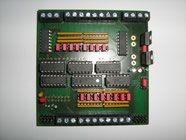
Board I:
8 Analog input 0-10V or 0-24V
8 Analog output 0-10V or 0-24V
The concept is to use the analog input / output as digital input / output if required. This might be a waste of an AD or DA converter, but it simplifies the concept and for that reason I think this is OK.
The latest version is equipped with amplifier for analog output and for analog input, to be able to connect NTC and PTC temperature probes.
Board III (in preparation- 80% finished):
8 Analog input 0-10V or 0-24V
8 Analog output 0-10V or 0-24V
H Bridge for 2 DC Motors forward / backward variable speed, or 1 step motor.
Can be used as standalone PIC18 Microcontroller board for Hobby / Development
Board II (in preparation- delayed):
4 Anloge Input 4..20mA
4 Anlage Output 4..20mA
The connection to the Raspberry PI is done via the two SPI bus. The new board III for motor control and analog /dig I/0 will have the options SPI or I2C. USB would also be possible, but needs some software development.
In the Board I, SPI1 is used for contol the chip select signal via a MPC23S08 to the 8 chanel AD converter MCP3008 or the four 2 channel DA converter MCP4912.
SPI2 is used to enable the selected AD or DA converter.
In theory an endless number of expansion boards can be connected in a row to one single Raspberry PI. The Chip - Select can be AND - Connected directly to the signal of the Raspi or to a signal from a previous board. This is to avoid mixed up CS-Signals during switching of the addresses of the boards.
Alternatively a fixed number of Expansion boards can be used parallel. The Chip select to the MPC23S08 is then connected to the GPIO of the Raspberry PI instead of direct using the SPI CS Signal. An advantage of this mode is, that the communication is much faster.
The Board III Comunicates directly with a PIC18F25K50 Microcontroller which is connected to analog output via SPI bus and on board Analog input.
Status of the Procject
Hardware:
- Expansion board I: 0-10V / 0-24V has been designed and a prototype has been tested.
The Board ist ready for download as an KICad project or PDF as a mask for etching. - Expansion board II: 4..20mA input / Output is in preparation - delayed
- Expansion board III: Hardware is designed, and prototype tested. Firmware needs some more development
Todo:
- Development of an Input / output board of different kinds of temperature probes like PT100, PT1000, KTY, Type K, Type J
Software:
- Basic functionality of a single board has been tested.
- Software of communicate with the board through the SPI bus has been written in Gambas, Python and C and can be downloaded in the download page.
Todo:
- Database connection of the driver
- Implementing USB for Board III
- Improving SPI performance for Board III
- Finish to implement I2C to board III