NEW DEVELOPMENT - Board III
For Analog I/0 and Motor Control
June 2017: After a long break I continued to work on the expansion board with good progress. The hardware platform seems to be finished now, just need some more testing. The firmware of the PIC makes also good progress and can be released soon.
February 2nd 2017: Basic design is finished, the hardware is working OK. Software development on the firmware of the PIC18F25K50 is in progress to communicate with the Raspberry PI.
Update Jan 6th 2015: The PCB of the expansion board came from manufacturing throught Beta Layout. Now it needs to be soldered and tested.
Update Jan 11th 2015:The expansion board has been completed and tested. Some issues occured which makes a redesign with smaller changes necessary. After the redesign I will offer a download of the Kicad Project and PDF files for self - manufacturing the PCB.
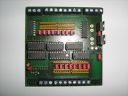
Update Jan 18th 2015: I eliminated the issues from the test, so that I can offer the download soon. Below is a picture of the latest version. I also made a board for 4..20mA, but also faced some issues which require a new testboard, before I can offer the download.
Jan 18th 2015: This is the almost ready prototype. Because of a mistake, only 4 our of 8 channels are working.
Update March 7th: I found a bug in the design which requires to disconnect the leg 9 of the 49x2 - Chip. There will be a redesign soon which eliminates this issue. A temporary fix is to pinch off the SHDN - Pin, which is accedantely connected to GND.
Update March 25th: I elimated the bug. Meanwhile I tested to connect 2 boards to the SPI bus. The software was a bit tricky but finally it works.
Update April 5th: I tested the new Rasperry Pi 2 board with the latest design of the expansion board. It works very well. I did not make serious performance test, but my impression is, that this
is a big improvement for the performance.
Update April 6th: I added on the download page a Howto for configuring the Raspberry PI to work with the expaqnsion board
Update April 20th: I added mounting holes to the PCB, which fits to the Raspberry PI Model B. It can be used to assemble the PI on top of the Expansion board.
Update April 26th: The expample program spitest.c is now ready for download. It uses ioctrl to comunicate with the expansion board.
UPdate June 21st: An example for usage of multiple boards in seral configuration is available. It is tested with 2 boards, however in theory the number of boards is not
limitted.
Update October 4th 2015: A new revision of my board with input amplifier is in test now. It makes the temperature meassurement with NTC easy and I use it now since 4 weeks to meassure the
performance of the central heating of our house. In the next days I will order a new prototype and if this works fine, I will call it the final version of the 10V / 24 V analog inpout / output
board.
Update October 27th 2015: The latest version No. 3.3 works satisfactory, so that I call it the final version. Might be that in the future I will do smaller chages for a different housing, but
technically it works fine.

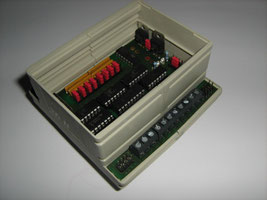
The board fits into a cap rail housing.


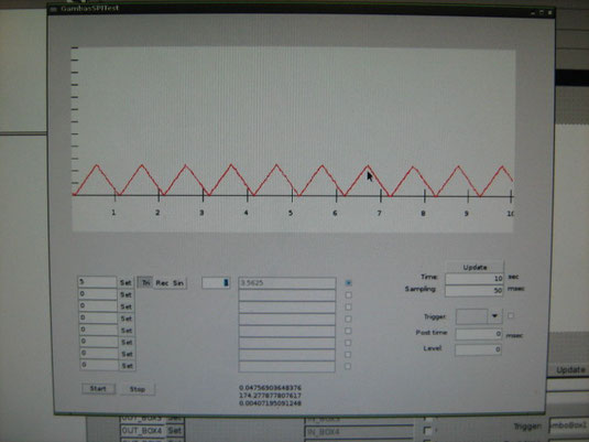
This is an example program for the OS expansion board: A simple Oszilloscope and function generator. It will easily help to understand how to use the expansion board with your own software.